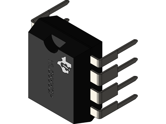
The 555 timer is a popular integrated circuit that is widely used in various electronic projects. It is a versatile device that can be used for different applications, such as oscillators, timers, and flip-flops. The 555 timer has eight pins, each of which serves a specific function.
Pin 1 of the 555 timer is the ground pin. It is connected to the negative terminal of the power supply and provides a reference voltage for the other pins. Pin 1 is also used for decoupling, which involves connecting a capacitor between pin 1 and the positive supply voltage to stabilize the voltage.
Pin 2 is the trigger pin, which is used to initiate the timing cycle. When the voltage on this pin drops below one-third of the supply voltage, the output of the 555 timer switches from high to low, and the timing cycle begins. Pin 2 is usually connected to a resistor and a capacitor to create a time delay.
Pin 3 is the output pin, which produces a square wave with a duty cycle that depends on the values of the external components. The output voltage swings between the positive supply voltage and ground, and it can source or sink up to 200mA of current.
Pin 4 is the reset pin, which is used to reset the timing cycle to its initial state. When a negative pulse is applied to this pin, the output of the 555 timer goes low, and the timing cycle starts again.
Pin 5 is the control voltage pin, which is used to adjust the threshold and trigger levels of the 555 timer. By applying a voltage between 0.7V and 2/3Vcc to this pin, the threshold and trigger levels can be set to different values.
Pin 6 is the threshold pin, which is used to determine the end of the timing cycle. When the voltage on this pin exceeds two-thirds of the supply voltage, the output of the 555 timer switches from low to high, and the timing cycle ends. Pin 6 is usually connected to a resistor and a capacitor to create a time delay.
Pin 7, the discharge pin, is connected to the open collector of a transistor, which is used to discharge the timing capacitor during the timing cycle. When the output of the 555 timer is low, the transistor is turned on, and the capacitor is discharged through the transistor to ground.
Pin 8, the threshold pin, is connected to the non-inverting input of a comparator that compares the voltage at the threshold pin to a reference voltage. When the voltage at the threshold pin exceeds two-thirds of the supply voltage, the comparator output goes high and triggers the output of the 555 timer to go low, which turns on the discharge transistor through pin 7 and begins the timing cycle.
Together, pins 7 and 8 work in conjunction to control the timing cycle of the 555 timer. When the voltage at the threshold pin reaches the two-thirds level, the output of the 555 timer goes low and the capacitor at pin 6 begins to charge. When the voltage on the capacitor reaches the one-third level, the output of the 555 timer goes high, and the discharge transistor at pin 7 is turned off, which stops the timing cycle and allows the capacitor to discharge through an external resistor.
The Timer Circuits
The 555 timer is a popular integrated circuit (IC) that can be used to generate accurate and stable timing signals for a wide range of electronic applications. It was first introduced in 1971 by Signetics Corporation, and has since become one of the most widely used ICs in the electronics industry.
The 555 timer is a versatile device that can be configured to operate in a variety of modes, including monostable, astable, and bistable modes. In the monostable mode, the 555 timer functions as a one-shot pulse generator, where a single output pulse is generated in response to an input trigger. In the astable mode, the 555 timer functions as a free-running oscillator, where a continuous series of output pulses are generated. In the bistable mode, the 555 timer functions as a flip-flop, where the output state is toggled between two stable states in response to an input trigger.
The basic circuit diagram of a 555 timer is shown below:
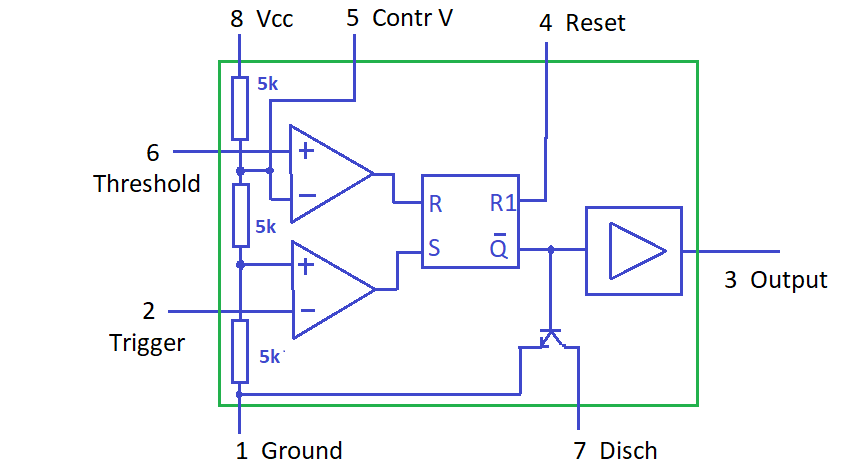
The 555 timer consists of three main components: two comparators, a flip-flop, and an output stage. The comparators compare the input voltage to a voltage reference, and the flip-flop sets and resets the output stage based on the state of the comparators. The output stage drives the output pin, which can be used to control external circuitry.
To illustrate the operation of a 555 timer, let’s consider the astable mode circuit shown below:
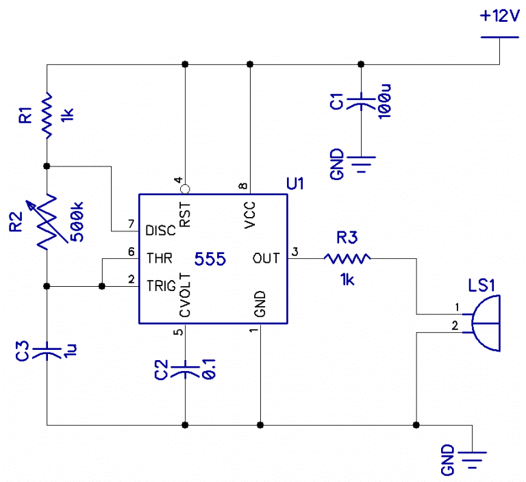
In this circuit, the 555 timer is configured as an astable oscillator, where the output pin (pin 3) produces a continuous stream of pulses. The frequency and duty cycle of the output pulses are determined by the values of the resistors (R1 and R2) and capacitor (C1) in the circuit.
When power is applied to the circuit, capacitor C1 begins to charge through resistor R1. When the voltage across the capacitor reaches two-thirds of the supply voltage, the flip-flop changes state, and the output pin goes high. The capacitor then begins to discharge through resistor R2 until the voltage across the capacitor reaches one-third of the supply voltage, at which point the flip-flop changes state again, and the output pin goes low.
The time period of the output pulse (T) is given by the formula:
T = 0.693 x (R1 + R2) x C1
The duty cycle (D) of the output pulse is given by the formula:
D = R2 / (R1 + R2)
By selecting appropriate values for R1, R2, and C1, it is possible to generate output pulses with a wide range of frequencies and duty cycles.
In conclusion, the 555 timer is a versatile and widely used IC that can be used to generate accurate and stable timing signals for a variety of electronic applications. Its simple design and ease of use make it a popular choice among hobbyists and professionals alike.
In summary, the 555 timer is a versatile device that has eight pins, each of which serves a specific function. Pin 1 is the ground pin, pin 2 is the trigger pin, pin 3 is the output pin, pin 4 is the reset pin, pin 5 is the control voltage pin, and pin 6 is the threshold pin. By using external resistors and capacitors, the 555 timer can be configured to perform different tasks, such as generating oscillations or producing time delays.